Siggraph 2018: The Road toward Unified Rendering with Unity’s High Definition Render Pipeline

The slides of my and Evgenii Golubev talk “The Road toward Unified Rendering with Unity’s High Definition Render Pipeline” in the advance realtime rendering course at Siggraph 2018 are available here:

http://advances.realtimerendering.com/s2018/index.htm

This talk is about the architecture of Unity’s High Definition Render Pipeline (HDRP – Lighting, Material, Decal) from a high level perspective and it provide some implementation details about our BRDF and volumetric lighting algorithm.

The initial goal of this talk was to share as much as possible the new stuff that we have develop for HDRP. It appear that there was really too much to say and too little time. I have already added several slides that was not show during the Siggraph presentation (Which explain a bit why some transition are not smooth :)), but initially there was way more. Will need to do more talk about it to cover them, but will try to go more in depth next time.

I will try during the next few month to provide more implementation details on my blog as slides format don’t allow to be as verbose as course notes. I started with a short blog post about GBuffer packing function. Given that all the source code of HDRP is available here: https://github.com/Unity-Technologies/ScriptableRenderPipeline I feel a bit less guilty of only having scratching the surface of some concept like surface gradient framework (That I highly recommend to adopt) – Also for this one it is Morten Mikklesen that should write a blog post about it!

In this talk, I was willing to discuss the lighting, material and decals architecture from high level perspective to highlight that when we try to do thing “correctly” and within performance constrain, there is not so much flexibility left. I like the example of deferred decal as this is a topic I often heard about. Why do you not support deferred decal, they are so performant ?
Having decal working correctly with material for baked GI is currently not easy and solution like deferred decal are full of mess (in addition to be a nightmare for blend state combination) and they don’t work in forward rendering.

I also was willing to promote an architecture that support features parity between forward and deferred path. Showing what are the technical constrain and how this is convenient for performance comparison (When you are a generalist engine).

Once thing I haven’t discuss in the talk and will do here is the limitation of the “correctness” of screen space reflection (SSR). Artists always ask this feature whatever the engine they work on.

SSR is part of the reflection hierarchy (SSR, planar reflection, reflection probe, sky) and is very helpful to perform specular occlusion at the same time. It is often implemented as a gaussian blur (trying to mimic GGX) with parameter normal, roughness and F0 that are store in a Buffer (usually 2 render target of the GBuffer).
For performance reasons this pass is always done separately from the main lighting loop and often in async compute. This mean that the only available parameters are those output in the buffer. And this is where thing get messy.
The benefit of forward is to allow to implement complex BRDF, like anisotropic layered material. But then, the multiple normal and multiple roughness don’t fit inside the buffer use for SSR! What does it mean in practice?
This mean that inside the reflection hierarchy, wherever you have SSR (i.e in several location of the screen), your nice lighting model like coating simply disappear as it is replace by some kind of gaussian BRDF. There is not really alternative here. We could perform the SSR pass inside the light loop itself. In this case correct implementation could be perform with using multiple raymarching for different normal etc… But this is obviously impractical from performance point of view.
So SSR is nice, as long as the lighting model match the simple Gaussian model that it try to mimic. We hit here the limitation of screen space method and our only salvation will be real time raytracing as already highlight by many 🙂

Errata in the presentation:

  • Slide 33: “Ambient occlusion apply on static lighting during GBuffer pass if no RT5” = > “Ambient occlusion apply on static lighting during GBuffer pass if no RT4”

At the same course there is also the talk of Evgenii Golubev about “Efficient Screen-Space Subsurface Scattering Using Burley’s Normalized Diffusion in Real-Time” which discuss about the Disney SSS method we develop for HDRP.
GBuffer helper – Packing integer and float together

Version : 1.0 – Living blog

With GBuffer approach, it is often required to pack values together. One useful case is to be able to pack an integer value (often matching an enum like material ID) and a float value (inside 0..1 range).

For example in Unity High Definition Render Pipeline we have pack inside the GBuffer:

  • DiffusionProfile (16 values) and Subsurface Mask (Float 0..1)
  • Material Features (8 values) and Coat Mask (Float 0..1)
  • Quadrant for tangent frame (8 values) and metallic (Float 0..1)

During development we have change several times the number of bit required for our packing and it quickly come to us that we were needed to have general packing functions to encode arbitrary values. This is the topic of this short blog post.

Let’s say that we want to encode a Mask on 1 bit with a Scalar in range 0..1 with 8 bit of precision inside a shader. Mean in practice we pack both values in a component of a RGBA 32bit render target. Remember that the float value in the shader is convert at the end of the pipeline to corresponding render target format, in our case the float value will be multiply by 255 to fit into the 8bit precision of the component. We will have 7 bits to encode the float, this could be perform with a simple remapping:

(127.0 * Scalar)  / 255.0

multiply by 127 (or (1 << 7) – 1) which is 01111111 in binaries leave 1 bit available for the Mask.
Then we divide by 255.0
Then we need to add the bit for the mask itself at the 8th position mean value of 128 (or (1 << 8) – 1)

(128.0 * Mask) / 255.0

So encoding is

Val = (127.0 / 255.0) * Scalar + (128.0 / 255.0) * Mask

Decoding should be the reverse of the operation above. First we need to retrieve the Mask value

Mask = int((255.0 / 128.0) * Val)

Note that here we use the int cast to remove all the Scalar value part.
For example if we have Scalar of 0 and Mask with 1, Val is suppose to be 128.0 / 255.0.
Mean the above code give us 1
if Scalar is 1, Val is suppose to be 1.0, mean Mask = int(1.9921875) = 1. All good.
We then retrieve the value of Scalar

Scalar = (Val - (128.0 / 255.0) * float(Mask)) / (127.0 / 255.0)

Now let’s consider a RGBA1010102 render target with a Mask on 4 bit. The process is exactly the same.
First remap value to cover 6 bit for the float value and 4 bit for the Mask value

Val = (63.0 / 1023.0) * Scalar + (64.0 / 1023.0) * Mask

For example if Mask is 2 (i.e 128.0 / 1023.0) and Scalar is 1.0 we get 0010 1111 11 as binaries representation.
4 bit for Mask then 6 bit for Scalar.
For decoding we first retrieve the Mask then the Scalar

Mask = int((1023.0 / 64.0) * Val)
Scalar = (Val - (64.0 / 1023.0) * float(Mask)) / (63.0 / 1023.0)

Important addition.
Due to rounding and floating point calculation on GPU it may appear that Mask reconstruction is shifted by one value.
This can be fixed by adding the smallest epsilon allowed by the render target format. i.e

Mask = int((1023.0 / 64.0) * Val + 1.0 / 1023.0)

We can easily generalize this process for any unsigned render target format and any Mask size. Here are the functions to do the work.

float PackFloatInt(float f, uint i, uint numBitI, uint numBitTarget)
{
    // Constant optimize by compiler
    float precision = float(1 << numBitTarget);
    float maxi = float(1 << numBitI);
    float precisionMinusOne = precision - 1.0;
    float t1 = ((precision / maxi) - 1.0) / precisionMinusOne;
    float t2 = (precision / maxi) / precisionMinusOne;

    // Code
    return t1 * f + t2 * float(i);
}

void UnpackFloatInt(float val, uint numBitI, uint numBitTarget, out float f, out uint i)
{
    // Constant optimize by compiler
    float precision = float(1 << numBitTarget);
    float maxi = float(1 << numBitI);
    float precisionMinusOne = precision - 1.0;
    float t1 = ((precision / maxi) - 1.0) / precisionMinusOne;
    float t2 = (precision / maxi) / precisionMinusOne;

    // Code
    // extract integer part
    // + rcp(precisionMinusOne) to deal with precision issue
    i = int((val / t2) + rcp(precisionMinusOne));
    // Now that we have i, solve formula in PackFloatInt for f
    //f = (val - t2 * float(i)) / t1 => convert in mads form
    f = saturate((-t2 * float(i) + val) / t1); // Saturate in case of precision issue
}

// Define various variants for ease of use and code read
float PackFloatInt8bit(float f, uint i, uint numBitI)
{
    return PackFloatInt(f, i, numBitI, 8);
}

void UnpackFloatInt8bit(float val, uint numBitI, out float f, out uint i)
{
    UnpackFloatInt(val, numBitI, 8, f, i);
}

float PackFloatInt10bit(float f, uint i, uint numBitI)
{
    return PackFloatInt(f, i, numBitI, 10);
}

void UnpackFloatInt10bit(float val, uint numBitI, out float f, out uint i)
{
    UnpackFloatInt(val, numBitI, 10, f, i);
}

float PackFloatInt16bit(float f, uint i, uint numBitI)
{
    return PackFloatInt(f, i, numBitI, 16);
}

void UnpackFloatInt16bit(float val, uint numBitI, out float f, out uint i)
{
    UnpackFloatInt(val, numBitI, 16, f, i);
}

And example usage:

// Encode
outSSSBuffer0.a = PackFloatInt8bit(sssData.subsurfaceMask, sssData.diffusionProfile, 4);
// Decode
UnpackFloatInt8bit(inSSSBuffer0.a, 4, sssData.subsurfaceMask, sssData.diffusionProfile);

// Encode
outGBuffer2.a  = PackFloatInt8bit(coatMask, materialFeatureId, 3);
// Decode
float coatMask;
uint materialFeatureId;
UnpackFloatInt8bit(inGBuffer2.a, 3, coatMask, materialFeatureId);

Siggraph 2017: Physically-Based Materials: Where Are We?

The slides of my talk “Physically-Based Materials: Where Are We?” in the open real-time rendering course at Siggraph 2017 are available here:

http://openproblems.realtimerendering.com/s2017/index.html

This talk is about current state of the art of physically based material in real time rendering and what could be done in the future.
Often people tend to say that material rendering is a solve problem, but we are very far to have solved it. And the main reason is that we even don’t know what is a true/correct model for a physically based material.

Note: I forget to mention in the slides 56-57 where I compare the anisotropic GGX with reference that I use Disney remapping for anisotropy parameter.

// Ref: http://blog.selfshadow.com/publications/s2012-shading-course/burley/s2012_pbs_disney_brdf_notes_v3.pdf (in addenda)
// Convert anisotropic ratio (0->no isotropic; 1->full anisotropy in tangent direction) to roughness
void ConvertAnisotropyToRoughness(float roughness, float anisotropy, out float roughnessT, out float roughnessB)
{
    // (0 <= anisotropy <= 1), therefore (0 <= anisoAspect <= 1)
    // The 0.9 factor limits the aspect ratio to 10:1.
    float anisoAspect = sqrt(1.0 - 0.9 * anisotropy);

    roughnessT = roughness / anisoAspect; // Distort along tangent (rougher)
    roughnessB = roughness * anisoAspect; // Straighten along bitangent (smoother)
}

The conclusion of my talk is that a future BRDF could be:

Layered BRDF: 2 specular BRDF + Diffuse BRDF
– All derives from the same anisotropic NDF
– Energy conserving: MultiScattering, Fresnel interfaces
– Option to switch to Airy reflectance Fresnel
– Shape-invariant “matching measure” NDF
– Multiscale Diffuse and Specular representation

Other than the two last points, I think we can approximate such BRDFs for realtime in two years (next console generation ?).
To extent a bit, here I think a good BRDF could be an anisotropic GGX diffuse lobe + two anisotropic GGX specular lobe (one for hazy and one for sharp) + one isotropic coat GGX lobe. Added to that an option to replace Fresnel term of base specular layer by Airy reflectance. Multiscattering specular/diffuse should be possible in real time with precomputed table. Approximation for Fresnel interfaces should be possible given some constrain and chosing a physical representation. Diffuse and specular roughness should be separated. Complex IOR for metal should use the artists friendly 2 color model of Framestore.
The true challenge being to be light coherent. i.e have a good approximation of the interaction of this model with area light, image based light and GI.

But what is interesting is the consequence of such a choice. With 2 parameter for diffuse roughness, 5 for specular roughness, RGB diffuse, 2x RGB specular color, 1 for coat specular: 17 parameters solely for BRDF without normal map, AO, SO… And with the growing adoption of VR and 4k, I predict that forward engine will be the norm in the future. Not necessary for game, but maybe for the growing demand of real time movie.

Originally I wanted to cover current state of physically based rendering (Material, lighting and camera). Due to lack of time I have switch to Material only (volume, surface, character BRDF etc…) and , again, due to lack of time, I have restrict myself to “common” material. Then reduced it to only opaque reflective material (no transparency)… Too much thing to cover!

PBR is a huge unsolved topic and when I heard people saying, “yes, we are PBR”, I just heard “I have no clue what PBR mean”. And I am not confident myself that I understand what PBR really mean 🙂

Siggraph 2016: An Artist-Friendly Workflow for Panoramic HDRI

The slides and course notes files of me and my-coworker Sébastien Lachambre and Cyril Jover “An Artist-Friendly Workflow for Panoramic HDRI” are available here:

On the official PBR course website:
http://blog.selfshadow.com/publications/s2016-shading-course/

and Unity Labs website:
https://labs.unity.com/

On the asset store of Unity there is a pack of HDRI. This is a pack of 7 LatLong, 8192×4096 HDR images shot in different locations around the world. Accurate, unclamped cubemaps of interior and exterior environments; HDRIs that include the Sun are provided with an alternate version with the Sun already removed. https://www.assetstore.unity3d.com/en/#!/content/72511
Note: HDRI can be download in Unity then use in another context, they are just .exr files. There is no restriction on both commercial and non-commercial usage for them.

Few notes:
As a programmer, I was often asking myself how artists are capturing HDRI ? After few research I have noticed that very often the HDRI available on the Internet lack range or metadata information to reconstruct absolute HDRI. Worse, many HDRIs are tweaked to looks good instead of being accurate to be used as a light sources. With my co-worker we have decided to write an extensive “tutorial” that explain how to capture an accurate HDRI. We have voluntary provide a lot of details and our equipment/software recommendation list. We hope by this to save readers time when they will try to reproduce our workflow. We have consider our workflow from an artists point of view instead of a programmer point of view, trying to use commonly know artist softwares. We also limit ourselves to average budget for this kind of capture.

The course notes (~80 pages) is the interesting part of the talk, the slide are just here to give an overview. I have included a section about what I call the “path of light”. It explain what is happening inside a camera from an emit photon to its life through the optics, the sensor, then the software processing. This is not something that is needed to understand to apply our method. But it is a really interesting piece of knowledge and help to put correct words on thing :).

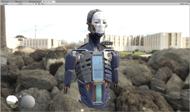
Lastly in the course note I have decided to integrate a section call “Look Development”. Look development is a term pretty common in VFX industry but I was surprise to see how few people know about it in the game industry. At Unity we have develop a new tools call “Look Dev” that will be experimental in the next version 5.5 beta. This is a viewer that aim to help look development with HDRIs:

Lookdev

Of course, this kind of tools already exist, Substance, Marmoset, Mari, etc… The benefit of having one integrated into Unity is that it is WYSIWYG (What you see is what you get) in your Unity game.

Finally I have chose to add some digression about how to remove the sun and replace it with analytic directional light of similar intensity as it is often either not discuss or resume to a single sentence in others documents. This is currently a complex topics and I will be happy to see more technical discussion around this topics.

We hope that our document will help people to take their first steps into accurate HDRI capture and see more absolute HDRI appearing. The document come with some materials: Various Photoshop Actions that we use and set of HDRIs. One is available on publications website but we expect to deliver soon a package of HDRI via the Unity Asset Store for free that include all versions (white balance, absolute, unprocessed…) of an HDRI and metadata.  At first we were willing to distribute all the CR2 too but the size of the download become crazy insane and we think to do it only for one HDRI, so programmer willing to do some test will be able to do it.

Siggraph 2014 : Moving Frostbite to Physically based rendering V3

Here is the slides, course notes and Mathematica files of me and my-coworker Charles de Rousiers “Moving Frostbite to Physically based rendering” (The course notes have been update to v3, mathematica files to v3):

Course notes: course_notes_moving_frostbite_to_pbr_v3
Pdf Slides: s2014_pbs_frostbite_slides
PowerPoint Slides: s2014_pbs_frostbite_slides
Mathematica Notebooks: movingfrostbitetopbr-mathematicanotebook_v3
Mathematica Notebooks export as pdf to be readable without Mathematica: movingfrostbitetopbr-mathematicapdf_v3

Caution : Both Mathematica files are .zip that I rename to “.pdf” as WordPress don’t support zip file. So just right-click on the image below, save the pdf file then change the extension to “.zip”,

Slideshare version:

Alternatively the files are/was available at others location (Let here in case links are update):
http://www.frostbite.com/2014/11/moving-frostbite-to-pbr/
And also on the official PBR course website:
http://blog.selfshadow.com/publications/s2014-shading-course/ (To be update only slides for now)

The talk is a survey of current PBR technics and small improvement we have done for the Frostbite engine. It covert many topics. Here is the table of content of the course note (available on linked website):

1 Introduction
2 Reference
2.1 Validating models and hypothesis
2.2 Validating in-engine approximations
2.3 Validating in-engine reference mode
3 Material
3.1 Material models
3.2 Material system
3.3 PBR and decals
4 Lighting
4.1 General
4.2 Analytical light parameters
4.3 Light unit
4.4 Punctual lights
4.5 Photometric lights
4.6 Sun
4.7 Area lights
4.8 Emissive surfaces
4.9 Image based lights
4.10 Shadow and occlusion
4.11 Deferred / Forward rendering
5 Image
5.1 A Physically Based Camera
5.2 Manipulation of high values
5.3 Antialiasing
6 Transition to PBR

v2 Update:
During a year, we have get several feedbacks from various people on our document (Sorry we forget to do a list of all of them). There was several mistakes, typo and unclear statement. We have upgrade the course note with all the reported error and clarified some part. The v2 course contain the following list of correction (Also listed on page 98 in the new course note pdf document):

– Section 3.2.1 – Corrected wrong statement for describing the micro-specular occlusion of the Reflectance parameters: ”The lower part of this attribute defines a micro-specular occlusion term used for both dielectric and metal materials.”. Description of BaseColor and Reflectance parameters have been updated.
– Section 3.2.1 – Removed reference on Alex Fry work of normal encoding as it has not been done.
– Section 4.2 – Updated the description of color temperature for artificial lights sources. Including the concept of color correlated temperature (CCT).
– Section 4.4 – Clarified what is lightColor in Listing 4
– Section 4.5 – Clarified what is lightColor in Listing 5
– Section 4.6 – Updated and explained the computation of the Sun solid angle and the estimated illuminance at Earth surface.
– Section 4.7.2.2 – Added comment in Listing 7: FormFactor equation include a invPi that needs to be canceled out (with Pi) in the sphere and disk area light evaluation
– Section 4.7.2.2 – Clarified in which case the diffuse sphere area formula is exact above the horizon
– Section 4.7.2.3 – Clarified in which case the diffuse disk area formula is exact above the horizon
– Section 4.7.4 – Correct listing 15. getDiffuseDominantDir parameter N is float3
– Section 4.7.5 – Correct listing 16. getSpecularDominantDirArea parameters N and R are float3
– Section 4.9.2 – Corrected the PDF of the specular BRDF and equations from 48 to 60. They had missing components or mistakes. The code was correct.
– Section 4.9.3 – Correct listing 21/22/23. getSpecularDominantDir parameters N and R are float3. getDiffuseDominantDir parameters N and V are float3
– Section 4.9.5 – Added and update comment about reflection composition: The composition weight computation for medium range reflections was causing darkening if several local light probes were overlapping. The previous algorithm was considering that each local light probes visibility was covering a different part of the BRDF lobe (having 10 overlapping local light probes of 0.1 visibility result in 1.0). The new algorithm considers that it covers the same part of the BRDF lobe (Adding 10 overlapping local light probes of 0.1 visibility result in 0.1).
– Section 4.10.2 – Corrected listing 26. Roughness and smoothness were inverted. The listing have been updated and an improve formula have been provided. Figure 65 has been updated accordingly.
– Section 4.10.2 – Added a reference to “Is Accurate Occlusion of Glossy Reflections Necessary” paper.
– Section 5.2 – Table~\ref{tab:SmallFloat}: Fixed wrong largest value for 14-bit float format. 16-bit float format is a standard floating point format with implied 1 on the mantissa. Max exponent for 16-bit float is 15 (not 16, because 16 is reserved for INF). Largest value is (1+m)^{maxExp} = (1+\frac{1023}{1024})*2^{15} = 65504. Whereas 14-bit float format has no leading 1, but a max exponent of 16. Largest value is m*2^{maxExp} = (\frac{511}{512})^{16} = 65408. 10-bit and 11-bit float format follow same rules as 16-bit float format.

v3 Update:
– Section 5.1.1 – Fix equation 67

Few notes

Last year I was giving a talk about Remember Me at GDCEurope 2013 : The art and rendering of Remember Me. And I was saying: Read more of this post