Image-based Lighting approaches and parallax-corrected cubemap
September 29, 2012 26 Comments
Version : 1.28 – Living blog – First version was 2 December 2011
This post replace and update a previous post name “Tips, tricks and guidelines for specular cubemap” with information contain in the Siggraph 2012 talk “Local Image-based Lighting With Parallax-corrected Cubemap” available here.
Image-based lighting (IBL) is common in game today to simulate ambient lighting and it fit perfectly with physically based rendering (PBR). The cubemap parameterization is the main use due to its hardware efficiency and this post is focus on ambient specular lighting with cubemap. There is many different specular cubemaps usage in game and this post will describe most of them and include the description of a new approach to simulate ambient specular lighting with local image-based Lighting. Even if most part of this post are dedicated to tools setup for this new approach, they can easily be reuse in other context. The post will first describe different IBL strategies for ambient specular lighting, then give some tips on saving specular cubemap memory. Second, it will detail an algorithm to gather nearest cubemaps from a point of interest (POI), calculate each cubemap’s contribution and efficiently blend these cubemaps on the GPU. It will finish by several algorithms to parallax-correct a cubemap and the application for the local IBL with parallax-cubemap approach. I use the term specular cubemap to refer to both classic specular cubemap and prefiltered mipmapped radiance environment map. As always, any feedbacks or comments are welcomed.
IBL strategies for ambient specular lighting
In this section I will discuss several strategies of cubemap usage for ambient specular lighting. The choice of the right method to use depends on the game context and engine architecture. For clarity, I need to introduce some definitions:
I will divide cubemaps in two categories:
– Infinite cubemaps: These cubemaps are used as a representation of infinite distant lighting, they have no location. They can be generated with the game engine or authored by hand. They are perfect for representing low frequency lighting scene like outdoor lighting (i.e the light is rather smooth across the level) .
– Local cubemaps: These cubemaps have a location and represent finite environment lighting.They are mostly generating with game engine based on a sample location in the level. The generated lighting is only right at the location where the cubemap was generated, all other locations must be approximate. More, as cubemap represent an infinite box by definition, there is parallax issue (Reflected objects are not at the right position) which require tricks to be compensated. They are used for middle and high frequency lighting scene like indoor lighting. The number of local cubemap required to match lighting condition of a scene increase with the lighting complexity (i.e if you have a lot of different lights affecting a scene, you need to sample the lighting at several location to be able to simulate the original lighting condition).
And as we often need to blend multiple cubemap, I will define different cubemap blending method :
– Sampling K cubemaps in the main shader and do a weighted sum. Expensive.
– Blending cubemap on the CPU and use the resulted cubemap in the shader. Expensive depends on the resolution and required double buffering resources to avoid GPU stall.
– Blending cubemap on the GPU and use the resulted cubemap in the shader. Fast.
– Only with a deferred or light-prepass engine: Apply K cubemaps by weighted additive blending. Each cubemap bounding volume is rendered to the screen and normal+roughness from G-Buffer is used to sample the cubemap.
In all strategies describe below, I won’t talk about visual fidelity but rather about problems and advantages.
Object based cubemap
Each object is linked to a local cubemap. Objects take the nearest cubemap placed in the level and use it as specular ambient light source. This is the way adopted by Half Life 2 [1] for their world specular lighting.
Background objects will be linked at their nearest cubemaps offline and dynamic objects will do dynamic queries at runtime. Cubemaps can have a range to not affect objects outside their boundaries, they can affect background objects only, dynamic objects only or both.
The main problem with object based cubemap is lighting seams between adjacent objects using different cubemaps.
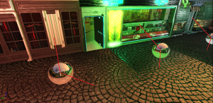
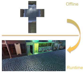
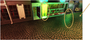
Here is a screenshot (click for full res)
On this screenshot you can see cubemaps linked offline to several objects (the red lines). Lighting seams occur on the ground when parts of the ground are assign to different cubemap. This is obvious in this screenshot because the lighting is high frequency. Another problem is that you need to split a mesh into several parts when it is shared by two different environments, which is common for objects like walls and floors. It adds production constraints on meshes. Note that nearest cubemap is not always the right choice. Visibility should be test in some case.
Some advices for the cubemap placement with this method are describeb here [2]:
If a cubemap is intended for NPCs or the player, the env_cubemap should be placed at head-height above the ground. This way, the cubemap will most accurately represent the world from the perspective of a standing creature.
If a cubemap is intended for static world geometry, the env_cubemap should be a fair distance away from all brush surfaces.
A different cubemap should be taken in each area of distinct of visual contrast. A hallway with bright yellow light will need its own env_cubemap, especially if it is next to a room with low blue light. Without two env_cubemap entities, reflections and specular highlights will seem incorrect on entities and world geometry in one of the areas.
(…)
Because surfaces must approximate their surroundings via cubemaps, using too many cubemaps in a small area can cause noticeable visual discontinuities when moving around. For areas of high reflectivity, it is generally more correct to place one cubemap in the center of the surface and no more. This avoids seams or popping as the view changes.
The other problem is that you need to track which cubemap affect dynamics object. As dynamic object can swap their cubemap, there is popping. Popping can be reduced by blending the K nearest cubemap of the dynamic object. This is rather an expensive solution, you can blend the K cubemaps in the shader, adding a lot of instruction and fetch. But even blending K nearest cubemap will not prevent the popping induce by switching the smallest contributing cubemap when there is more than K cubemaps present.
Zone based cubemap
An infinite cubemap is assigned for each zone of the level. When the camera enters in a zone, the infinite cubemap from the zone is applied on all objects. Killzone 2/3, Call of duty: black ops, Prey 2 for sample use this method [3][7][19].
This method is simple to implement and fit with any engine architecture. There are no lighting seams between objects as the same cubemap is used for all objects and cubemaps need to be blend between zones to avoid popping. Cubemap can be blended efficiently on CPU/GPU or in a deferred way with the 2 cubemaps processed at the same time.
Global and local cubemap no overlapping
All objects used a global (infinite in this case) cubemap by default. Some local cubemap are placed into the level with no overlapping range. When the camera or the player reaches the range of a local cubemap, all objects used this local cubemap instead of the global cubemap.
This method is similar in spirit to zone based cubemap except that “zone” has not the same definition. Cubemap can be blended efficiently on CPU/GPU or in a deferred way with the 2 cubemaps processed at the same time. Frostbite engine (Battlefield 2) uses only a global cubmap for representing the skylight [4].
I am not sure of the method used to represent outdoor (global)/indoor (local) lighting in Frosbite 2 engine (Battlefield 3) [5]. But they use sky visibility to blend between indoor cubemap and outdoor cubemap, which look similar to this strategy.
Global and local cubemap overlapping
Global (infinite in this case) and local cubemap affect only objects in their range (defined by artists). Objects can be affected by several overlapped cubemap, like a global and a local cubemap.
This strategy can only be implemented efficiently with a deferred or light-prepass rendering architecture.
This is the method used by Cryengine 3 (Crysis 2) [6] . This method is simple to implement in a deferred context, the cubemap are blended in a deferred way. There can be lighting seams at the boundary of the cubemap.
Point of interest (POI) based cubemap (Siggraph 2012 talk)
Several local cubemap are placed in the level. The number of local cubemap depends on the lighting complexity. Then the K-nearest cubemap of the POI are blended and the result is applied on all objects.
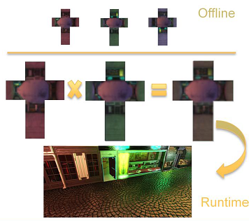
The POI depends on the context, it can be the camera, the player or any characters in the scene. It could be a dummy location animated by a track for in game cinematic.
I develop this method for a forward renderer with complex lighting scene as I can’t rely on the Global/Local overlapping method due to engine architecture constraint. This approach has been presented in the Siggraph 2012 talk : “Local Image-based Lighting with parallax corrected cubemap”.
With this method, there are no seams at all, as K cubemap are always blended. Then you always have only one cubemap applied on objects. Like for dynamic objects in the object based method, popping can appear when switching the smallest contributing cubemap when there is more than K cubemaps present (Also artists should be able to avoid it). The two main problems of this approach are the parallax issue caused by local cubemaps, which can be even worse when blending multiple cubemaps, and the inaccurate lighting on distant object; lighting accuracy decreases with distance from POI as the approximated lighting environment is done at POI.
The parallax artifact are fix with the method describe at the end of this post and the inaccurate lighting on distant object is reduce by using one of the following method (which can be use for the Global and local cubemap no overlapping strategy too):
- Use ambient lighting information at object position (like lightmaps or spherical harmonics) and mix it with the current cubemap contribution based on distance from POI (Similar technique are use to save memory and they are describe in the section “Reusing available cubemap” later in this post).
- Apply an attenuation of the specular contribution with the distance from the POI. For almost mirror objects (like pure metal in the context of PBR), this can be a problem as the diffuse color will be black. In this case an option should be provide to disable the attenuation for this object and fall back to method above. Note that this can be share with share LOD technique and help with performance.
- Override the cubemap (See below).
Common to several strategies
With all strategies, objects should be able to force the usage of a predefined cubemap. This allow to set high resolution cubemap on mirror object [8], fix visual artifacts with always distant mirror objects, or any other similar needs.
For method based on zone (Zone based and Global and local cubemap no overlapping), the blending of cubemap could be time-based rather than zone distance-based.
Added note:
In the context of PBR:
– With a light-prepass renderer, deferred cubemaps will not have access to the specular color term required by the Fresnel equation.
– With a forward renderer, cubemaps are rendered at the same time as objects and can access all material attributes.
– With a deferred renderer, cubemaps can be rendered forward at G-Buffer time (with emissive store in G-buffer) or deferred later and can access all material attributes store in G-buffer.
– With deferred cubemap, we can’t access to ddx/ddy texcoord and so we can’t perform the mipmap optimization which consists to take the lesser lod between manual and hardware lod.
It is possible to add some dynamic responses to lighting environment by switching on/off cubemaps. Several cubemaps must be generated under different lighting condition, and they can be switched based on context, or even blended.
Specular cubemaps memory footprint
Having a lot of cubemaps require a lot of storage. Unlike irradiance cubemap which can be very low resolution (16x16x6 or 8x8x6) a specular cubemap is rather middle resolution (64x64x6 or 128x128x6). Higher resolution (256x256x6 or 512x512x6) may even be required for mirror objects. This section will discuss some methods to help with the memory footprint of cubemaps.
Texture compression and streaming
The most obvious advice when talking about saving memory with textures is to implement a streaming textures system and choose an aggressive texture compression format.
Streaming cubemaps is a more complicated problem than what we can think at first. The simplest strategy is to have infinite/local cubemaps link to a zone and load them with the zone. Streaming only high mipmap of cubemap when required suppose that you know when you will need it, which is not trivial and this require hardware cubemap layout knowledge.
About the compression format, the cubemap should be HDR (If you generate the cubemap in game engine remember to switch off the postprocess, then you may require to not applying cubemap on objects when capturing a new cubemap). As we talk about games on DX9/XBOX360/PS3 generation, we must fit in a RGBA8bit format at most.
There are few candidates : YCoCg [24], LogLuv, Luv, RGBE, RGBM of any kind [9][11][12] or Cryengine 3 RGBK (like RGBM)[6]; All are stored as DXT5 and require extra instructions. As I need a lot of cubemaps of medium quality with the less extra instructions possible, I choose the aggressive HDR format describe in [10]. A good alternative will be to let the artists choose the compression format and to automatically default to the compression format which best fit the required range (Like RGBE for a very large range). For the aggressive format, the HDR cubemap compress to a sRGB DXT1 which is compact (half the cost of any DXT5 RGBM) and it require really few instructions to decompress.
The method is to calc the maximum values of each channel (R, G and B) of all texels of the cubemap, clamped to a threshold. Divide each texel by this maximum value. Then store the result in sRGB DXT1 :
// Sample for R channel but same code for other.
// MaxPixelColor is the Max of the 3 RGB channels in the whole cubemap
StorageColor.R = Clamp(SrcPtr[0], 0.0f, MAX_HDR_CUBEMAP_INTENSITY);
StorageColor.R = MaxPixelColor > 0.0f ? StorageColor.R / MaxPixelColor : 0.0f;
StorageColor.R = ConvertTosRGB(StorageColor.R);
Compression quality depends on cubemap content and MAX_HDR_CUBEMAP_INTENSITY. I chose 8 for MAX_HDR_CUBEMAP_INTENSITY which effectively give MDR rather than HDR. The result is good enough for my needs. As a simple comparison: a 1024×1024 DXT1 texture take same memory as ten 128x128x6 DXT1 cubemap.
In the shader, you just have to do a multiply to recover the original range. The multiply is done in linear space after the hardware sRGB decompression:
half3 CubeColor = texCUBElod(CubeTexture, half4(CubeDir, MipmapIndex)).rgb;
half3 FinalCubeColor  = CubeColor * MaxPixelColor;
Advice: You can choose to compress each channel with its own channel maximun instead of using the maximun of the three channels. In this case, care must be taken about the difference between channel maximun (i.e your three maximun are very different values like R:8, G:1, B:1). When the difference between maximun is high, compressing the channel individually cause a perceptual hue error. Here is an example of a lightprobe generated in a scene with a highly bright red light causing maximun color to be R:8, G:1.5, B:1.5. The lightprobe should be grey everywhere expect for the light (not show here):
Here the compression of the Red channel by 8 introduce error in the decompression compare to the two other channel which cause a red shift (Compare with the image below). If you instead chose the maximun of the three values for the compression (i.e 8), you get this:
This is perceptually closest to the right result because all channels are compress with the same value and introduce the same error, so no hue shift, however the decompression is less accurate. To sum up, compressing with three individual channel are more accurate, it better conserve luminance, but in case of high difference between maximun it cause hue shift; compressing with maximun of the three channel is less accurate but do not produce hue shift. Better is to let the control to the artists.
Reusing available cubemap
The best way to save memory is to reuse cubemap. The exact content of a cubemap matter less than its average color and intensity [10]. So we want to perform some modifications of an original cubemap to match the lighting environment at a given location. These modifications allow reusing a cubemap at several place instead of generating a new cubemap for each new location. There is several ways to do that:
– “Normalizing” cubemap as describe in [10]
“normalizing” the environment map (dividing it by its average value) in a pre-process, and then multiplying it by the diffuse ambient in the shader. The diffuse ambient value used should be averaged over all normal directions, in the case of spherical harmonics this would be the 0-order SH coefficient.
– Multiply by ambient lighting ratio:
All cubemaps must be generated in engine. At the generation time, get the diffuse ambient (as define above). When reusing the cubemap at a new location, get the new diffuse ambient then modulate cubemap by the ratio (“new diffuse ambient” / “old diffuse ambient”).
– Mixing based on gloss:
This way is describe in the comment of this post by Brian Karis: With low gloss value, use the color of the lightmap * intensity of cubemap. With high gloss value, it is the reverse, intensity of lightmap * color of cubemap. Both cases use a normalized cubemap and modulate.
– Desaturate the cubemap :
Convert cubemap to grey scale luminance, then recolorize with the diffuse ambient (average color of ambient lighting). Note that with this method, you have only one channel to store cubemap. Battlefield 3 [5] use this kind of approach. They store some black and white cubemap in one RGBA8 cube texture (one for glass, one for weapons, etc…) and they modulate with the ambient lighting given by their dynamic radiosity system.
– Color correct the cubemap [3]:
Apply any color correction which will allow matching the new location. Color correction can take the form of curve (highlight, midtown, shadow), simple color modulation, desaturation etc…
Killzone 2 [15] can specify a color multiplier and a desaturate factor by zone to apply on the cubemap sample (And they can multiply by SH sample too in a way similar to previous methods).
The diffuse ambient is often take from SH Lightprobe or dynamic radiosity, but it can be taken by pixel from the lightmaps.
All these way have similar drawbacks. They all fail with complex scene lighting consist of many different colored light. Of course, the fail is not too hard and will probably not be noticed by player, but your only choice to be fully accurate is to generate more cubemap. These ways could also be use to minimize artifact with POI-based approach.
Local cubemaps blending weights calculation
Several strategies based on local cubemap like the POI-based cubemap method require retrieving the K nearest local cubemap of the POI and blend them together. The problem of getting the K nearest cubemap is similar to the SH irradiance volume problem. [13][20][21] Give sample of interpolation method for solving it. However, for specular cubemap, as you can’t have so much lightprobe in your level, simpler algorithm are preferable. I use an octree for this. The blending calculation can be trickier if you want to avoid popping and this section will describe one method I develop for local cubemaps (which mean cubemaps with a location).
The algorithm aiming to work with influence volume associate to each cubemap store in an octree. This will allow gathering cubemap close to the POI efficiently. If the current POI is outside of influence volume, the cubemap will not be taken into account. This implies that for smooth transition, influence volumes must overlap. We provide artists with boxes and spheres influences volumes. Using only spheres may cause large overlap that we want to avoid. Think about several corridors in a U shape on different floors.
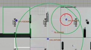
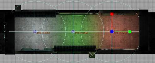
The figure shows a top view of a toy level with 3 cubemap volumes overlapping in green. One square, two spheres. The red circle represents an inner range. When the POI is in inner range, it gets 100% contribution of the cubemap. If no inner range is defined, this is the center of the influence volume.The inner range was an artist’s request.
In order to not to have any lighting pop, we define a set of rules that our algorithm must follow, including artists’ request. The cubemap will have 100% influences at boundary of an inner range and 0% at boundary of outer range. So the influence volume weights follow a pattern similar to distance fields but inversed and normalized.
We also add the rule that a small volume inside another bigger volume must contribute more to the final result but should respect previous constraints. This allows artists to increase accuracy in a localized region.
In the following we define the variable “NDF” (normalized distance field) as 0 at inner range boundary and 1 at outer range boundary, < 0 if inside inner range. The algorithm starts by gathering all the influence volumes intersecting the POI position. For each influence volumes it calculates the volume influence weight (the NDF value). Selected influence volumes are then sorted by most influential. Then for each selected influence volumes, we calculate the sum of volume influence weights and the sum of the inverse. These sums are then used to get two results. The first result enforces the rule that at the boundary we have 0% contribution and the second enforces the rule that at the center we have 100% contribution, whatever the number of overlapping primitives. We then modulate the two results. To finish, all blend factors are normalized. Here is the pseudo-code:
Box::GetInfluenceWeights()
{
    // Transform from World space to local box (without scaling, so we can test extend box)
    Vector4 LocalPosition = InfluenceVolume.WorldToLocal(SourcePosition);
    // Work in the upper left corner of the box.
    Vector LocalDir = Vector(Abs(LocalPosition.X), Abs(LocalPosition.Y), Abs(LocalPosition.Z));
    LocalDir = (LocalDir - BoxInnerRange) / (BoxOuterRange - BoxInnerRange);
    // Take max of all axis
    NDF = LocalDir.GetMax();
}

Sphere::GetInfluenceWeights()
{
    Vector SphereCenter            = InfluenceVolume->GetCenter();
    Vector Direction               = SourcePosition - SphereCenter;
    const float DistanceSquared    = (Direction).SizeSquared();
    NDF = (Direction.Size() - InnerRange) / (OuterRange - InnerRange);
}

void GetBlendMapFactor(int Num, CubemapInfluenceVolume* InfluenceVolume, float* BlendFactor)
{
    // First calc sum of NDF and InvDNF to normalize value
    float SumNDF            = 0.0f;
    float InvSumNDF         = 0.0f;
    float SumBlendFactor    = 0.0f;
    // The algorithm is as follow
    // Primitive have a normalized distance function which is 0 at center and 1 at boundary
    // When blending multiple primitive, we want the following constraint to be respect:
    // A - 100% (full weight) at center of primitive whatever the number of primitive overlapping
    // B - 0% (zero weight) at boundary of primitive whatever the number of primitive overlapping
    // For this we calc two weight and modulate them.
    // Weight0 is calc with NDF and allow to respect constraint B
    // Weight1 is calc with inverse NDF, which is (1 - NDF) and allow to respect constraint A
    // What enforce the constraint is the special case of 0 which once multiply by another value is 0.
    // For Weight 0, the 0 will enforce that boundary is always at 0%, but center will not always be 100%
    // For Weight 1, the 0 will enforce that center is always at 100%, but boundary will not always be 0%
    // Modulate weight0 and weight1 then renormalizing will allow to respects A and B at the same time.
    // The in between is not linear but give a pleasant result.
    // In practice the algorithm fail to avoid popping when leaving inner range of a primitive
    // which is include in at least 2 other primitives.
    // As this is a rare case, we do with it.
    for (INT i = 0; i < Num; ++i)
    {
        SumNDF       += InfluenceVolume(i).NDF;
        InvSumNDF    += (1.0f - InfluenceVolume(i).NDF);
    }

    // Weight0 = normalized NDF, inverted to have 1 at center, 0 at boundary.
    // And as we invert, we need to divide by Num-1 to stay normalized (else sum is > 1).
    // respect constraint B.
    // Weight1 = normalized inverted NDF, so we have 1 at center, 0 at boundary
    // and respect constraint A.
    for (INT i = 0; i < Num; ++i)
    {
        BlendFactor[i] = (1.0f - (InfluenceVolume(i).NDF / SumNDF)) / (Num - 1);
        BlendFactor[i] *= ((1.0f - InfluenceVolume(i).NDF) / InvSumNDF);
        SumBlendFactor += BlendFactor[i];
    }

    // Normalize BlendFactor
    if (SumBlendFactor == 0.0f) // Possible with custom weight
    {
        SumBlendFactor = 1.0f;
    }

    float ConstVal = 1.0f / SumBlendFactor;
    for (int i = 0; i < Num; ++i)
    {
        BlendFactor[i] *= ConstVal;
    }
}

// Main code
for (int i = 0; i < NumPrimitive; ++i)
 {
     if (In inner range)
         EarlyOut;

     if (In outer range)
        SelectedInfluenceVolumes.Add(InfluenceVolumes.GetInfluenceWeights(LocationPOI));
 }

SelectedInfluenceVolumes.Sort();
GetBlendMapFactor(SelectedInfluenceVolumes.Num(), SelectedInfluenceVolumes, outBlendFactor)
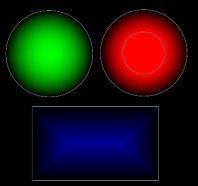
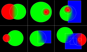
Here is result for different situation. Each influence volume is represented by a color (2 circles: Red, green and a box : Blue). The weights are represented by the blending of the respective color of each influence volume. A pure red mean 100% contribution, a 50% red mean 50% contribution from the red influence volume. Inner ranges are represented by small influence volume with a white line inside bigger influence volume of the same color. Click for high res:
The image above highlight that there is no popping with common situation and that we fully respect the rules we set. The algorithm even provides a pleasant transition. It however fails in some stressful condition we rarely met. In case you want to play with it, here is a link of the RenderMonkey project I use for generate this image: Siggraph_NormalizedDistance (This is a .pdf file as wordpress don’t support .zip file, right click and select save the link as then rename the file to .rfx after download).
There is also a video showing the influence volume edition and associated debugging tools here : Local Image-based Lighting With Parallax-corrected Cubemap : Influence volume .
Added note:
Other more complex method like Delauney triangulation [13][21] or Voronoi diagram could be used, but I found this one simple and efficient.
Kill zone 2 for sample used a simple distance based interpolation [14] for their SH lightprobe interpolation.
Thanks to my co-worker Antoine Zanuttini for providing me the base RenderMonkey project I used to generate the picture.
Efficient GPU cubemaps blending
The POI-based cubemap method, in the context of a forward renderer, requires an efficient way of blending multiple cubemaps (including mipmaps). When dealing with multiple cubemaps, it can be costly to blend them inside the objects shader (And even more when dealing with parallax-corrected cubemap as explain at the end of this post). Instead, we chose to blend cubemaps on CPU or GPU separately in a step before the main rendering.
In this section, I will describe a pseudo DX9 implementation method to efficiently blend multiple cubemaps on GPU. For more real usage case, the code comes with the HDR cubemap format I use. This allows seeing the performance linked to this particular format.
The goal is to generate a new cubemap, based on K weighted cubemap. For this method, all your cubemap required to be the same size (128x128x6 here). The algorithm is simple:
 For each face
    For each mipmap of the resulting cubemap
        Setup the current mipmap face as the current rendertarget
        Render the weighted sum of current mipmap of the K cubemaps
I will not details the DX9 creation of the cubemap. You need to create a cube texture and save a surface pointer on each of the mipmap of each face of the cubemap. The following pseudo implementation describe the main blending loop:
const int CubemapSize    = 128;
int         SizeX        = CubemapSize;
const int NumMipmap      = 7;

for (int FaceIdx = 0; FaceIdx < CubeFace_MAX; FaceIdx++)
{
    // The mipmap follow each other in memory, so used this order
    for (INT MipmapIndex = 0; MipmapIndex < NumMipmap; ++MipmapIndex)
    {
        SizeX = CubemapSize >> MipmapIndex;
        Direct3DDevice->SetRenderTarget(BlendCubemapTextureCube->CubeFaceSurfacesRHI[FaceIdx * NumMipmap + MipmapIndex]);
        // No alpha blending, no depth tests or writes, no stencil tests or writes, no backface culling.
        Direct3DDevice->SetRenderState(...)
        // Write in rendertarget as sRGB for the agressive HDR format in place
        Direct3DDevice->SetRenderState(D3DRS_SRGBWRITEENABLE,TRUE);
        SetBlendCubemapShader(FaceIdx, MipmapIndex);
        DrawQuad(0, 0, SizeX, SizeX);
    }
}
The cubemap rendertarget destination is RGBA8bit for performance, so we need to compress the result. I use the hardware sRGB to read from blended HDR cubemap and to write in the resulting HDR cubemap which allow saving some instructions. I generate a shader for each face of the cubemap for efficiency (Each of them have a different define for FACEIDX, see shader code below). The SetBlendCubemapShader in the code above will select the shader for the current face and set the current mipmap index. The shader code is in charge to sample each of the texel of the K cubemap and blend them. Here is the code:
#define FACE_POS_X 0
#define FACE_NEG_X 1
#define FACE_POS_Y 2
#define FACE_NEG_Y 3
#define FACE_POS_Z 4
#define FACE_NEG_Z 5

void BlendCubemapVertexMain(
    in float4 InPosition : POSITION,
    out float4 OutPosition : POSITION
    )
{
    OutPosition = InPosition;
}

half4    VPosScaleBias;
half     MipmapIndex;

samplerCUBE BlendCubeTexture1;
samplerCUBE BlendCubeTexture2;
samplerCUBE BlendCubeTexture3;
samplerCUBE BlendCubeTexture4;

half    MaxPixelColor1;
half    MaxPixelColor2;
half    MaxPixelColor3;
half    MaxPixelColor4;

// Get direction from cube texel for a given face. x and y are in the [-1, 1] range.
half3 GetCubeDir(half x, half y )
{
    // Set direction according to face.
    // Note : No need to normalize as we sample in a cubemap
#if FACEIDX == FACE_POS_X
    return half3(1.0, -y, -x);
#elif FACEIDX == FACE_NEG_X
    return half3(-1.0, -y, x);
#elif FACEIDX == FACE_POS_Y
    return half3(x, 1.0, y);
#elif FACEIDX == FACE_NEG_Y
    return half3(x, -1.0, -y);
#elif FACEIDX == FACE_POS_Z
    return half3(x, -y, 1.0);
#elif FACEIDX == FACE_NEG_Z
    return half3(-x, -y, -1.0);
#endif
}

void BlendCubemapPixelMain(
    float2 ScreenPosition: VPOS,
    out half4 OutColor : COLOR0
    )
{
    float2 xy        = VPosScaleBias.xy * ScreenPosition.xy + VPosScaleBias.zw;
    half3 CubeDir    = GetCubeDir(xy.x, xy.y);

    // We come from sRGB to linear then we apply the multiplier
    half3 CubeColor1 = texCUBElod(BlendCubeTexture1, half4(CubeDir, MipmapIndex)).rgb;
    half3 CubeColor  = CubeColor1 * MaxPixelColor1;

    half3 CubeColor2 = texCUBElod(BlendCubeTexture2, half4(CubeDir, MipmapIndex)).rgb;
    CubeColor        += CubeColor2 * MaxPixelColor2;

    half3 CubeColor3 = texCUBElod(BlendCubeTexture3, half4(CubeDir, MipmapIndex)).rgb;
    CubeColor        += CubeColor3 * MaxPixelColor3;

    half3 CubeColor4 = texCUBElod(BlendCubeTexture4, half4(CubeDir, MipmapIndex)).rgb;
    CubeColor        += CubeColor4 * MaxPixelColor4;

    OutColor         = half4(CubeColor / 8, 1.0f); // the convert to sRGB is done when writing in the rendertaget
}
FACEIDX is a define set to the current face to blend, each different value mean a different shader.
MaxPixelColorX are the constant use to decompresses HDR cubemap after the hardware decompress the sRGB value. Note the divide by 8 (which is the constant MAX_HDR_CUBEMAP_INTENSITY) at the end of the shader. To save instruction I just divide by the max range allowed and the result is store in RGBA8 (But you can use the max of all MaxPixelColor for more accuracy). So when using the result of the blending in other shader, the MaxPixelColor must be set to 8.
MipmapIndex is the current blended mipmap .
VPosScaleBias are four values allowing to transform from VPOS register to a [-1..1] interval required by the GetDir() function. This could be done in the shader, but for efficiency, the transform are baked in the VPosScaleBias. The VPOS register and the GetDir() allow to retrieve the direction to use to sample the blended cubemap. Here is the code for the VPosScaleBias setup :
// We need to transform VPOS in [-1, 1] range on X and Y axis.
float InvResolution = 1.0f / float(128 >> MipmapIndex); // 128 is the size of the cubemap
// transform from [0..res-1] to [- (1 - 1 / res) .. (1 - 1 / res)]
// VPos register is 0 left, RT_SizeX right and 0 Top, RT_sizeY bottom
// (UsePixelCenterOffset is 0.5 for DX9, 0 else)
Vector4 ScaleBias = Vector4(2.0f * InvResolution, 2.0f * InvResolution, -1.0f + (UsePixelCenterOffset * 2.0f * InvResolution), -1.0f + (UsePixelCenterOffset * 2.0f * InvResolution));
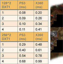
Here is tab showing the performance you can get with this method on PS3 and XBOX360. It requires the knowledge of the hardware layout on PS3 that I can’t detail here.
An alternative to this code is to render an infinite box from the 6 views of the resulting cubemap centered on the origin (0, 0, 0). Each cubemap are additively blended with their corresponding weight. Example code :
#define HALF_WORLD_MAX 262144.0
Matrix CubeLocalToWorld = ScaleMatrix(HALF_WORLD_MAX);
SetShader(...)
SetAdditiveBlending()

for each view of the blended cubemap
{
    for each mipmap
    {
        for each cubemap to blend
        {
            SetEnvMapScale(EnvMapScale * Blendweights);
            SetMipmapIndex(...);
            SetViewProjectionMatrix(CalcCubeFaceViewMatrix() * ProjectionMatrix);
            DrawUnitBox(...)
        }
    }
}

// In the shader

float4    MipmapIndex;
float4x4  LocalToWorld;
float4x4  ViewProjectionMatrix;
sampler2D BlendCubeTexture;
float3    EnvMapScale;

void BlendCubemapVertexMain(
    in float4 InPosition : POSITION,
    out float4 OutPosition : POSITION,
    out float3 UVW : TEXCOORD0
    )
{
    float4 WorldPos = mul( LocalToWorld, InPosition);
    float4 ScreenPos = mul( ViewProjectionMatrix, WorldPos);

    OutPosition = ScreenPos;
    UVW = WorldPos.xyz;
}

void BlendCubemapPixelMain(
    in float3 UVW : TEXCOORD0,
    out float44 OutColor : COLOR0
    )
{
    float3 CubeSample = texCUBElod(BlendCubeTexture, float4(UVW, MipmapIndex.x)).xyz;
    OutColor = half4(EnvMapScale.xyz * CubeSample / 8.0f, 1.0f);
}
The result is the same. Also, even if it look more simpler, the performance for one cubemap are the same but when using several cubemap, it is faster to use the previous method on PS3. So it depends on the context/platform.
Parallax correction for local cubemaps
As said in the first section, a cubemap represent an infinite box by definition. When used as a local cubemap, there is parallax issue (Reflected objects are not at the right position). This section explain some techniques that can be used to correct the parallax issue of a local cubemaps to better match the reflected objects placement.
The common point of every parallax-correction techniques is to define an approximation of the geometry (we will call this geometry proxy) surrounding the local cubemap. The simpler is the approximation, the more efficient will be the algorithm at the price of accuracy. Example of geometry proxy are sphere volume [16], box volume [17] or cube depth buffer [22]. Here is an example of a cubemap with an associated box volume in white.
In the shader, we perform an intersection between the reflection vector and the geometry proxy. This intersection is then use to correct the original reflection vector to a new direction. As the interaction must be performing in the shader, you can see how performance is linked to the choice of geometry proxy.
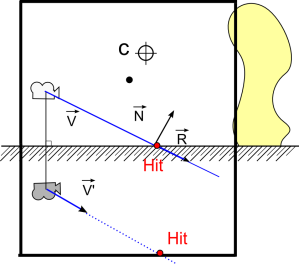
Here is an example of the algorithm with a simple AABB volume:
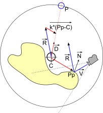
The hatched line is the reflecting ground and the yellow shape is the environment geometry. A cubemap has been generated at position C. A camera is looking at the ground. The view vector reflected by the surface normal R is normally used to sample the cubemap. Artists define an approximation of the geometry surrounding the cubemap using a box volume. This is the black rectangle in the figure. It should be noted that the box center doesn’t need to match the cubemap center. We then find P, the intersection between vector R and the box volume. We use vector CP as a new reflection vector R’ to sample the cubemap.
Here is the code, this is a simple box intersection with some simplifications:
float3 DirectionWS = PositionWS - CameraWS;
float3 ReflDirectionWS = reflect(DirectionWS, NormalWS);

// Following is the parallax-correction code
// Find the ray intersection with box plane
float3 FirstPlaneIntersect = (BoxMax - PositionWS) / ReflDirectionWS;
float3 SecondPlaneIntersect = (BoxMin - PositionWS) / ReflDirectionWS;
// Get the furthest of these intersections along the ray
// (Ok because x/0 give +inf and -x/0 give –inf )
float3 FurthestPlane = max(FirstPlaneIntersect, SecondPlaneIntersect);
// Find the closest far intersection
float Distance = min(min(FurthestPlane.x, FurthestPlane.y), FurthestPlane.z);

// Get the intersection position
float3 IntersectPositionWS = PositionWS + ReflDirectionWS * Distance;
// Get corrected reflection
ReflDirectionWS = IntersectPositionWS - CubemapPositionWS;
// End parallax-correction code

return texCUBE(envMap, ReflDirectionWS);
AABB volume is rather restricted and it is better to use an OBB volume instead. Here is a sample of implementation with an OBB volume :
float3 DirectionWS = normalize(PositionWS - CameraWS);
float3 ReflDirectionWS = reflect(DirectionWS, NormalWS);

// Intersection with OBB convertto unit box space
// Transform in local unit parallax cube space (scaled and rotated)
float3 RayLS = MulMatrix( float(3x3)WorldToLocal, ReflDirectionWS);
float3 PositionLS = MulMatrix( WorldToLocal, PositionWS);

float3 Unitary = float3(1.0f, 1.0f, 1.0f);
float3 FirstPlaneIntersect  = (Unitary - PositionLS) / RayLS;
float3 SecondPlaneIntersect = (-Unitary - PositionLS) / RayLS;
float3 FurthestPlane = max(FirstPlaneIntersect, SecondPlaneIntersect);
float Distance = min(FurthestPlane.x, min(FurthestPlane.y, FurthestPlane.z));

// Use Distance in WS directly to recover intersection
float3 IntersectPositionWS = PositionWS + ReflDirectionWS * Distance;
float3 ReflDirectionWS = IntersectPositionWS - CubemapPositionWS;

return texCUBE(envMap, ReflDirectionWS);
For each texel of the cubemap, we transform the corresponding view vector into a unit box space to perform the intersection. Note the optimization step when transforming the result back to world space to get the final corrected vector. Example result:

For an example with a sphere refer to [16].
Cheaper tricks exist to have a parallax effect. Also it requires tuning. It has been describe in [18] [23] and is also use in [8] and seems originated from Advanced Renderman book publish in 2000.
It consists to add a scaled version of the vector from the cubemap position C to the point on the object being draw Pp. The implementation is simple:
ReflDirectionWS= EnvMapOffset * (PositionWS - CubemapPositionWS) + ReflDirectionWS;
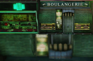
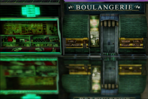
No need to normalize as we fetch into a cubemap. The EnvMapOffset is an artist’s tunable value which depends on objects size, size of the environment etc… Brennan in [23] uses (1 / radius) where radius is the radius of the sphere geometry proxy. Here is a sample of tuned parameter. First image is default, second is with EnvMapOffset tuned:
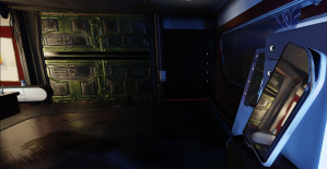
In the same spirit, Kill zone 2/3 use offset when sampling cubemap in order to change the “size” of the cubemap displayed inside an object [3].
Efficient GPU local parallax-corrected cubemap blending
I will now apply the result of the two previous sections with my POI-based approach. This is what I call : Local IBL approach with parallax-corrected cubemap. This approach has been develop by both me and my co-worker Antoine Zanuttini.
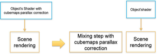
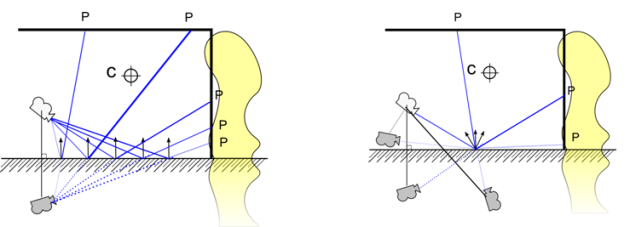
As detail in “Efficient GPU cubemap blending” section, we have a dedicated step for the blending of cubemap. We are looking for to parallax-correct the cubemap when blending them. However in this mixing step we don’t have access to the pixel position. To solve this, we made the following observation:
 The left figure represent our previous case of a simple box as geometry proxy for the parallax correction. What we observe, on the middle figure, if we add the view vector of the reflected camera V’ is that it matches the reflected view vector R. We can see that both vectors V’ and R intersect the same point P. This point P could be used like before to get a new reflection vector R’ to sample a cubemap. Right figure is the result of applying this reasoning to each view direction of a cubemap. We are now able to parallax-correct the whole cubemap without requiring any pixel position. We just require a reflection plane which substitute to the pixel position. However this will restrict our parallax-correction approach to planar objects.
Here is an example of the code for the mixing step which also handles the parallax-correction with box geometry proxy as we just see. The code only handles one face of the blended cubemap with only one cubemap (several cubemap is identical to the “Efficient GPU cubemap blending” section):
float4    VPosScaleBias;
float     MipmapIndex;
float4x4  WorldToLocal;
float3    ReflCameraWS;
samplerCUBE BlendCubeTexture;
float3    EnvMapScale;

void BlendCubemapPixelMain(
 float2 ScreenPosition: VPOS,
 out half4 OutColor : COLOR0
 )
{
 float2 xy        = VPosScaleBias.xy * ScreenPosition.xy + VPosScaleBias.zw;
 half3 CubeDir    = GetCubeDir(xy.x, xy.y);

 // Intersection with OBB convert to unit box space
 half3 RayWS = normalize(GetCubeDir(xy.x, xy.y)); // Current direction
 half3 RayLS = mul((half3x3)WorldToLocal, RayWS);
 half3 ReflCameraLS = mul(WorldToLocal, ReflCameraWS); // Can be precalc

 // Same code as before but for ReflCameraLS and with unit box
 half3 Unitary = half3(1.0f, 1.0f, 1.0f);
 half3 FirstPlaneIntersect    = (Unitary - ReflCameraLS) / RayLS;
 half3 SecondPlaneIntersect = (-Unitary - ReflCameraLS) / RayLS;
 half3 FurthestPlane = max(FirstPlaneIntersect, SecondPlaneIntersect);
 float Distance = min(FurthestPlane.x, min(FurthestPlane.y, FurthestPlane.z));
 // Use Distance in WS directly to recover intersection
 half3 IntersectPositionWS = ReflCameraWS + RayWS * Distance;
 half3 ReflDirectionWS = IntersectPositionWS - CubemapPositionWS;

 half3 CubeColor = texCUBElod(BlendCubeTexture, half4(ReflDirectionWS, MipmapIndex)).rgb;
 CubeColor       = CubeColor * EnvMapScale.xyz;
 OutColor         = half4(CubeColor / 8, 1.0f);
}
As in the “Efficient GPU cubemap blending” section we have an alternative way to get the same result. An alternative to this code is to render the box geometry proxy (instead of the infinite box) from the 6 views of the resulting cubemap from the point of view of the reflected camera (instead of the origin). Each cubemap are additively blended with their corresponding weight. But in this case we can do even better. Why limit ourselves to render in a box. With rasterization we can throw out the limitation on the shape and can start to handle convex volume! Concave volumes still have artifacts due to hidden features. For this, we allow our artists to define BSP geometry (with a brush tools in an editor for sample), and convert the bsp to triangle. Then render this triangle list instead of the simple box.
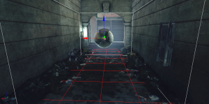
Here is an example of convex volume usage which fit the environment (right figure), in-place of a box volume (middle figure). Left figure show the original no corrected cubemap:
And here is the code to perform the parallax-correction for a convex volume. Shader code is for one face of the cubemap.
// C++
SetShader(...)
SetAdditiveBlending()

for each view of the blended cubemap
{
    for each mipmap
    {
        for each cubemap to blend
        {
            Matrix Mirror = CreateMirrorMatrix(ReflectionPlaneWS of this cubemap);
            Vector ReflectedViewPositionWS = Mirror.TransformVector(ViewPositionWS);
            SetEnvMapScale(EnvMapScale * Blendweights);
            SetMipmapIndex(...);
            SetViewProjectionMatrix(CalcCubeFaceViewMatrix(ReflectedViewPositionWS) * ProjectionMatrix);
            DrawConvexVolume(...);
        }
    }
}
// Shader
float4    MipmapIndex;
float4x4  LocalToWorld;
float4x4  ViewProjectionMatrix;
sampler2D BlendCubeTexture;
float3    EnvMapScale;
float3    CubemapPos;

void BlendCubemapVertexMain(
    in float4 InPosition : POSITION,
    out float4 OutPosition : POSITION,
    out float3 UVW : TEXCOORD0
    )
{
    float4 WorldPos = mul( LocalToWorld, InPosition);
    float4 ScreenPos = mul( ViewProjectionMatrix, WorldPos);

    OutPosition = ScreenPos;
    UVW = WorldPos.xyz - CubemapPos; // Current direction
}

void BlendCubemapPixelMain(
    in float3 UVW : TEXCOORD0,
    out float44 OutColor : COLOR0
    )
{
    float3 CubeSample = texCUBElod(BlendCubeTexture, float4(UVW, MipmapIndex.x)).xyz;
    OutColor = half4(EnvMapScale.xyz * CubeSample / 8.0f, 1.0f);
}
Note that even if we use a bsp as geometry proxy for the parallax correction, we still use simple box or sphere as influence volume to not overload the gathering cubemap algorithm.
With all this in hands, we can now apply the “Local IBL approach with parallax-corrected cubemap” approach. The steps are:
– Retrieve with the help of influence volume the closest cubemap from the POI
– Calc blending weight like in “Local cubemaps blending weights calculation”
– Perform the mixing step on the GPU with the convex parallax-correction blending code just above.
– Apply the result in the main pass as usual.
Here is a video example of the result with 3 cubemaps with 3 sphere influence volumes and box geometry proxy: Local IBL approach with parallax-corrected cubemap
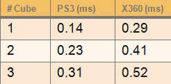
Now let’s see some performance result. Blending cubemaps with convex parallax-correction of 128x128x6 resolution in DXT1 give the following results:
It is useful to compare these numbers to the actual cost of applying the parallax-correction directly in the object’s shader (i.e in the main pass without a mixing step). Left number is for 25% screen coverage and right is for 75% screen coverage:
The number of the second table has been obtain by subtracting the cost of the parallax-correction shader with the original shader. Reading this result require some explanation. With the per pixel correction (i.e the second table), the result are depending on the screen coverage of the scene object. For 25% screen coverage each new cubemaps to mix is around 0.25ms and for 75% it is around 0.75ms on PS3. This is to compare to the mixing step approach where an additional cubemaps is only 0.08ms. It can be observe that for the per pixel correction, the XBOX perform better with one cubemap but drop more quickly by increasing the number of cubemaps. To sum up, our mixing approach better scale with many cubemaps.
Finally, the parallax-correction step describe above only work perfectly with mirror surface. Handling normal perturbation for glossy materials implies that we can access the lower hemisphere below the reflection plane. This means that our reflected camera’s view vector will miss the intersection with the box volume. To avoid this problem, artists must ensure that the reflected camera will always remain within the box volume:
Moreover, with glossy material, we introduce a distortion compared to the true result. The effect increases with the angle between the reflection plane normal and the perturbed normal.
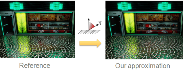 The source of this distortion is due to the way we generate our parallax-corrected cubemap. With our algorithm, the parallax-corrected cubemap is valid only for pixels with normals perpendicular to the reflection plane.
On the left figure several different intersections are calculated for different camera views. The entire ground surface has the same normal perpendicular to the reflection plane. On the right figure, we take the example of a single position and perturb its normal in different directions. In this case, the camera position needs to be moved. Our previous parallax-corrected camera is not able to provide the correct value in this case. We could generate a parallax-correct cubemap for this position for every possible normal but the result will be wrong for other positions.
Reference
[1] McTaggarts, “Half-Life 2 Valve Source Shading” http://www2.ati.com/developer/gdc/D3DTutorial10_Half-Life2_Shading.pdf
[2] http://developer.valvesoftware.com/wiki/Cubemaps
[3] Van Beek, “Killzone lighting pipeline” not available publicly
[4] Andersson, Tatarchuck, “Rendering Architecture and Real-time Procedural Shading & Texturing Techniques” http://www.slideshare.net/repii/frostbite-rendering-architecture-and-realtime-procedural-shading-texturing-techniques-presentation
[5] Magnusson, “Lighting you up in Battlefield 3” http://www.slideshare.net/DICEStudio/lighting-you-up-in-battlefield-3
[6] Sousa, Kasyan, Schulz, “Secrets of CryENGINE 3 Graphics Technology” http://advances.realtimerendering.com/s2011/SousaSchulzKazyan%20-%20CryEngine%203%20Rendering%20Secrets%20((Siggraph%202011%20Advances%20in%20Real-Time%20Rendering%20Course).ppt
[7] Karis, “comment” http://blog.selfshadow.com/2011/07/22/specular-showdown/#comments
[8] Gotanda, “Real-time Physically Based Rendering – Implementation” http://research.tri-ace.com/Data/cedec2011_RealtimePBR_Implementation.pptx
[9] “Unity RGBM toy” http://beta.unity3d.com/jcupisz/rgbm/index.html
[10] Hoffman, “Crafting Physically Motivated Shading Models for Game Development” and “Background: Physically-Based Shading” http://renderwonk.com/publications/s2010-shading-course/
[11] Kaplanyan, “CryENGINE 3: Reaching the Speed of Light” http://advances.realtimerendering.com/s2010/index.html
[12] Karis, “RGBM Color encoding” http://graphicrants.blogspot.com/2009/04/rgbm-color-encoding.html
[13] Cupisz, “LightProbe” http://blogs.unity3d.com/2011/03/09/light-probes/
[14] van der Leeuw, “The playstation3 spus in the real world” http://www.slideshare.net/guerrillagames/the-playstation3s-spus-in-the-real-world-a-killzone-2-case-study-9886224
[15] Personal communication with Michal Valient of Guerrilla game
[16] Bjorke, “Image Based-Lighting” http://http.developer.nvidia.com/GPUGems/gpugems_ch19.html
[17] behc, “Box Projected Cubemap Environment Mapping” http://www.gamedev.net/topic/568829-box-projected-cubemap-environment-mapping/
[18] Mad Mod Mike demo, “The Naked Truth Behind NVIDIA’s Demos” http://ftp.up.ac.za/mirrors/www.nvidia.com/developer/presentations/2005/SIGGRAPH/Truth_About_NVIDIA_Demos.pdf
[19] Lazarov, “Physically Based Lighting in Call of Duty: Black Ops”, http://advances.realtimerendering.com/s2011/Lazarov-Physically-Based-Lighting-in-Black-Ops%20(Siggraph%202011%20Advances%20in%20Real-Time%20Rendering%20Course).pptx
[20] Hall, Edwards, “Rendering in Cars 2”, http://advances.realtimerendering.com/s2011/Hall,%20Hall%20and%20Edwards%20-%20Rendering%20in%20Cars%202%20(Siggraph%202011%20Advances%20in%20Real-Time%20Rendering%20Course).pptx
[21] Cupisz, “Light probe interpolation using tetrahedral tessellations”, http://robert.cupisz.eu/stuff/Light_Probe_Interpolation-RobertCupisz-GDC2012.pdf
[22] Szirmay-Kalos, Aszódi, Lazányi, and Premecz, “Approximate Ray-Tracing on the GPU with Distance Impostors.”, http://sirkan.iit.bme.hu/~szirmay/ibl3.pdf
[23] Brennan, “Accurate Environment Mapped Reflections and Refractions by Adjusting for Object Distance.”, http://developer.amd.com/media/gpu_assets/ShaderX_CubeEnvironmentMapCorrection.pdf
[24] Van Waveren, Castaño, “Real-Time YCoCg-DXT Compression”, http://developer.download.nvidia.com/whitepapers/2007/Real-Time-YCoCg-DXT-Compression/Real-Time%20YCoCg-DXT%20Compression.pdf





Very cool and deep analysis!
Thank you for it!
Great post! Yes, for Prey 2 I use zone based. I cross fade over a short time whenever the selection changes. The artists much preferred object based that I was doing before but applying the cubemap full screen deferred was too large of an optimization to ignore so I had to switch to a single cubemap applied to everything. It did solve the seam problem which was a nice benefit but that wasn’t the reason for the switch. I did flirt with applying cubemaps with deferred volumes but I couldn’t make it fast enough to work out. The idea there to use a normal lerping blend instead of an additive like you would with lights. That way you guarantee 100% environment map contribution so long as there is at least one volume hitting everything. Eventually I got screen space reflections to work which fixed enough of the local reflection problems the artists had with the zone approach.
Maybe I missed where you mention it but there are popping issues with K closest and inverse squared contributions. When the smallest contributing cubemap switches there will be a small pop since it’s contribution only goes to zero if outside it’s range. If there are more than K in range you will get small pops. I had this very problem with my SH weighting.
Hi Brian,
Thank you for these informations!
I myself switch from object-based to camera-based to solve the seam problem. I try to fix the seam between object in object-based approach by modulating cubemap sample with lightmap texel (the ambient diffuse) but it was not a good solution for me.
And you are right, I missed to mention the popping issue with K nearest cubemap. For this issue, I am lazy, I let the artists deal with it 🙂
I update the post with your feedback, thanks a lot.
We do use normalized cubemaps and modulate by the lightmap like you mention. One neat trick we do with that is to take the color from the lightmap at low gloss and the color from the cubemap at high gloss. I wasn’t able to choose one over the other so I chose both 🙂
I am not sure I understand 🙂
Do you mean that you use normalized cubemap modulate by lightmap at low gloss and the color cubemap at high gloss ?
I mean that with low gloss it uses the color of the lightmap * intensity of cubemap. High gloss is the reverse, intensity of lightmap * color of cubemap. Both cases use a normalized cubemap and modulate so the average intensity is really just from the lightmap. The cubemap is giving it “texture”. This trick allows colored local lighting in low gloss and colored reflected objects in high gloss.
Little update in the “Specular cubemaps memory footprint” section. Changing from compressing 3 channel with 3 individual maximun to one maximun.
Add a link to a video : Local Image-based Lighting With Parallax-corrected Cubemap : Influence volume (http://www.youtube.com/watch?v=f8_oEg2s8dM)
Pingback: Unraveling DX Studio internals | egDev
Pingback: Parallax-corrected cubemapping with any cubemap | Interplay of Light
Very nice, thanks for sharing.
It’s really clever that technique you have there, and it really can replace dynamic flat reflections in many cases.
I have been trying to add this effect to unity(trying to speed up our game), and the axis aligned version is working fine. However, it would be best to get the obb version going.
My hlsl is somewhat sketchy, but I got the following:
void surf (Input IN, inout SurfaceOutput o)
{
o.Albedo = tex2D(_MainTex, IN.uv_MainTex);
float3 dir = IN.worldPos – _WorldSpaceCameraPos;
float3 worldN = IN.worldNormal;
float3 rdir = reflect (dir, worldN);
float3 ndir = normalize(dir);
float3 ReflDirectionWS = normalize (rdir);
float3 RayLS = mul((float4x4)_World2Object, float4(ReflDirectionWS,0));
float3 PositionLS = mul(_World2Object, float4(IN.worldPos.xyz,1));
float3 Unitary = float3(_EnvBoxSize.xyz/2); // Changed from (1,1,1) to match boxsize/2
float3 FirstPlaneIntersect = (Unitary – PositionLS) / RayLS;
float3 SecondPlaneIntersect = (-Unitary – PositionLS) /RayLS;
float3 FurthestPlane = max(FirstPlaneIntersect, SecondPlaneIntersect);
float Distance = min(FurthestPlane.x, min(FurthestPlane.y, FurthestPlane.z));
float3 IntersectPositionWS = IN.worldPos + ReflDirectionWS * Distance;
ReflDirectionWS = IntersectPositionWS – (_EnvBoxStart +_EnvBoxSize/2);
float3 Ref = texCUBE (_Cube, ReflDirectionWS);
o.Emission = Ref.rgb;
}
So, I had to change the Unitary value to half the box size, with (1,1,1) it looked very off, like a pinched reflection in a small cube.
Also, I was unsure of your value “RayWS”. The definition of this was not in your example further up. So I just used the normalized reflection direction.
So, the unity surface shader above “works”, except that the top reflection is pinched to a point. But it does get rotated correctly.
Any hints would be greatly appreciated.
Great work on the Remember Me game btw 🙂 Neo Paris looks awesome 🙂
Kjetil
Hey,
You spot an error in the code on this page, RayWS is ReflDirectionWS as you write.
Also you should write
float3 dir = IN.worldPos – _WorldSpaceCameraPos;
float3 worldN = IN.worldNormal;
float3 rdir = reflect (dir, worldN);
float3 ndir = normalize(dir);
float3 ReflDirectionWS = normalize (rdir);
=>
float3 ndir = normalize(IN.worldPos – _WorldSpaceCameraPos);
float3 worldN = IN.worldNormal;
float3 ReflDirectionWS = reflect (ndir, worldN);
if _World2Object include the scaling of the box, you must perform the intersection with unitary box and that should work (Just in case, non uniform scaling require a through inverse matrix code).
Hope that help
Cheers
1.28 – update OBB projection code
Pingback: Sphere Projected Cubemap Reflections | Popup Asylum
Pingback: 1 year | dontnormalize
Pingback: IBL |
Pingback: Planar Reflections & Area Lights
Pingback: Localized Reflection | PHrameBuffer
Really awesome work you did there. However I’m having some issues understanding how this reflected camera vector is obtained. Do I use a constant mirror plane normal (0, 1, 0) ? And this is my camera position that I mirror ?
Hey,
Which “reflected camera vector” are you referring too ?
I suppose you talk about the technique regarding convex volume where you need to specify a ground plane. In this case you reflect the camera position through this plane. This code is exactly the same than any mirror plane rendering.
Hope that help.
Hi there,
We’ve been using this box projection technique for some time in our title. We were surprised to find some cases where it would break down.
What would happen is when it picks the smallest distance out of the “FurthestDistance” float3, it would pick a negative distance. This would introduce a harsh, erroneous line across the reflection where it picked the negative distance from the wrong axis. On screen it would turn the reflection 90 degrees in one of the axes.
Putting in some simple code to replace the min operations with some code that would only take the minimum of the positive distances fixed the issue – negative distances were simply ignored. The image then looked correct.
Is this an issue you have encountered?
Thanks
Hey,
Are you applying localized cubemap in forward or in deferred ?
In which transform space are you working ? (Assume worldspace)
To have negative distance it mean that furthestPlane is negative, mean that max(firstPlaneIntersect, secondPlaneIntersect) have both negative number:
float3 firstPlaneIntersect = (boxMin – start) * invDir;
float3 secondPlaneIntersect = (boxMax – start) * invDir;
float3 furthestPlane = max(firstPlaneIntersect, secondPlaneIntersect);
intersections.y = min(min(furthestPlane.x, furthestPlane.y), furthestPlane.z);
which happen only if the start point is outside the box, mean you may have no intersection.
(code above extract from locals space test)
I have not encouter the issue you mention with the turn of reflection 90 degrees on one axes.
I am curious if you can provide image ? 🙂
Pingback: Screen Space Glossy Reflections | Roar11.com
Pingback: Image Based Lighting | Chetan Jags
Pingback: Assassins Creed 3 – Windows – 69 Tricks